
Home >>RC Airplane DIY Technology Article
How to assembly freewing f-22 raptor v2 90mm jet step by step
This guide applies to PNP V2 version (factory pre-installed servos, 90mm 12-blade EDF, 120A ESC, electric retracts, LED lighting).
Key V2 feature: Screwless Quick-Release Main Wings, reinforced vertical fins, full-flying horizontal stabilizers, integrated landing gear doors. Required tools: 1.5mm / 2.0mm hex screwdriver, foam-safe CA glue (optional), tape, servo horn pliers. Reference CG: 150 mm behind wing leading edge at wing root (official factory spec).
Pre-Assembly Step 0: Unbox & Inventory Check
- Lay out all parts on soft mat to avoid scratching EPO foam.
- Verify components:
- Main fuselage (pre-built with EDF, ESC, retract controller, wiring harness)
- Left / Right main wings (quick-release system, aileron + flap servos, LED lights)
- Left / Right vertical stabilizers (rudders, carbon reinforcement tubes, light wires)
- Left / Right full-flying horizontal stabilizers
- Magnetic nose cone, small scale foam/plastic detail parts
- Pushrods, ball links, all mounting screws
- Visually inspect all wiring, servos, retracts for shipping damage; check fan for foreign debris.
?? Do NOT power electronics until all mechanical assembly is finished.
Step 1: Install Vertical Stabilizers (Twin Rudders)
V2 Vertical Fin Carbon Tube
- Each vertical fin has an embedded carbon fiber reinforcement tube + LED/rudder servo extension wire.
- Route the vertical stabilizer wiring carefully through fuselage tail slot; pull wires out inside fuselage rear compartment.
- Insert carbon tube fully into matching fuselage socket, seat fin flush against fuselage surface.
- Secure each vertical fin with 2x KM3��10mm machine thread screws (V2 upgraded hardware).
- Connect fin wiring plugs to fuselage main harness; double-check polarity for navigation LEDs.
- Attach rudder pushrod between servo arm and rudder horn; secure ball links.
- Repeat for opposite vertical stabilizer. Ensure both fins are perfectly vertical & symmetrical.
Step 2: Mount Full-Flying Horizontal Stabilizers (Elevators)
- Retrieve metal rotating shafts, metal retaining rings, PM2��4mm set screws, washers.
- Slide metal fixed ring onto rotating shaft. Insert shaft through horizontal stabilizer mounting bore.
- Insert assembled shaft into rear fuselage horizontal tail mount.
- Secure shaft with 2�� PM2��4mm set screws (tighten gently, do not strip foam/plastic).
- Attach elevator pushrod between fuselage elevator servo and horizontal stabilizer horn.
- Repeat for second horizontal stabilizer.
- Manually test free movement of both elevators; confirm no binding across full travel.
Step 3: Install Quick-Release Main Wings (V2 Quick II System)
V2 Quick Release Wing Latch
Wing Ribbon Cable Connector
Wing Latch Operation Rule
- Unlock: Press switch fully down, release �� button pops up
- Lock: Press switch fully down, release �� button stays recessed (cannot pull wing out)
- Extend landing gear (via transmitter later; manually swing gear down for assembly clearance).
- Unlock both fuselage wing latches (press buttons, let pop up).
- Carefully pull the wide ribbon wiring harness out of fuselage wing root socket.
- Plug ribbon cable firmly into matching wing-side connector (align notch, do not force pins!).
- Slide main wing onto fuselage carbon support tube; push wing fully home until flush against fuselage.
- Press wing latch button down to LOCK. Gently tug wing outward to confirm locked securely.
- Repeat identical procedure for opposite wing.
?? Critical: Never pull the wing without unlocking latches; risk tearing ribbon wiring!
Step 4: Fit All Pushrods & Control Surfaces
All control surfaces use metal 1.2mm pushrods + ball link ends:
- Ailerons: Connect pushrod between wing aileron servo horn and aileron control horn.
- Flaps: Attach flap pushrods; set initial neutral position with flaps level with wing surface.
- Nose steering: Install 55mm nose gear steering pushrod to nose gear servo.
- Check every ball link: Snap closed securely; verify zero binding at full deflection.
- Adjust linkage length so all surfaces sit perfectly neutral when servos are centered.
Step 5: Fit Scale Exterior Details
- Nose cone: Simply push into front fuselage; internal magnets hold it securely (removable for transport).
- Install small foam fairings, exhaust nozzles, door covers at tail/rear fuselage using foam-safe CA glue (only if loose).
- Confirm landing gear door linkages move freely with retract operation.
Step 6: Radio Installation (PNP Version)
- Open large battery hatch below fuselage. Locate main MFCB wiring board.
- Mount receiver inside fuselage battery compartment (use double-sided foam tape; keep away from EDF motor to avoid EMI).
- Wire channel assignment (standard 7-channel setup):
- Ch1: Aileron
- Ch2: Elevator
- Ch3: Throttle (EDF)
- Ch4: Rudder
- Ch5: Landing Gear Retracts
- Ch6: Flaps
- Ch7: Optional Lights / Thrust Reverser
- Bind your radio transmitter to receiver.
- Double-check all servo plugs; verify no reversed polarity.
Step 7: Initial Power-On & Mechanical Test (NO BATTERY INTAKE NEAR FAN!)
- Connect flight battery (6S or 8S LiPo based on your motor variant).
- Turn on transmitter first, then aircraft power.
- Test sequence:
- Center all transmitter sticks; confirm all control surfaces sit neutral.
- Check aileron, elevator, rudder direction �C reverse channels in radio if movement is backwards.
- Test retracts: Cycle gear UP / DOWN multiple times; confirm doors open/close smoothly, no jamming.
- Deploy/retract flaps; check travel range.
- Test navigation/formation LEDs and nose taxi light.
- Briefly blip throttle at LOW power �C stand clear of EDF inlet/outlet.
? Keep hands, cables, debris far away from 90mm fan at all times when powered.
Step 8: Balance Aircraft (CG Check �C Mandatory Before First Flight)
- Remove nose cone, place battery inside battery bay.
- Balance jet at 150 mm aft of wing leading edge at wing root (official Freewing CG mark printed on lower wing).
- If nose heavy: Move battery backward; tail heavy: shift battery forward.
Tail-heavy F-22 is extremely unstable �C never fly without correct CG!
Step 9: Final Pre-Flight Inspection Checklist
? All wing latches locked, wings cannot slide out
? All ball links snapped closed
? No loose wiring near EDF fan
? Retracts and gear doors operate reliably
? Control surfaces move freely without binding
? CG verified
? All screws tight (do not over-tighten EPO foam)
? Check all wiring plugs are fully seated
Critical V2 Assembly Tips & Warnings
- Ribbon wing cable: Avoid sharp bending; disconnect wings gently for transport.
- Foam repairs: Only use foam-safe CA; regular superglue melts EPO.
- Landing gear: Do not taxi aggressively on rough pavement; suspension struts can bend.
- Thrust reverser (factory ESC): Set up in radio carefully; only activate during landing rollout.
- Transport: Unlock and remove both wings; detach magnetic nose cone to reduce length.
3.Freewing F-35 110mm EDF jet
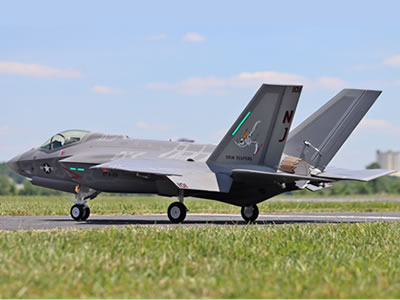
Freewing F-35C 110mm EDF Lightning II Super Scale Jet with Gyro RC Airplane

