
How to assemble Freewing F 35C 110 mm EDF Jet step by step in 2026
Step by Step Assembly Guide: Freewing F 35C 110 mm EDF Jet (PNP Gyro Version, Item FJ50111PG)
Freewing F-35C 110mm EDF jet manual(2026 new)
Freewing F-22 Raptor v2 90mm edf jet manual(2026 new)
Pre note: Most electronics (EDF, ESC, gyro, landing gear servos, LED wiring, fuselage servos) are pre installed in factory. Only airframe assembly, wiring plug ins, radio binding, battery fitting, control linkage tuning and CG setup are required.
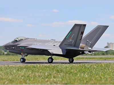
Freewing F-35C Lightning II Super Scale 110mm EDF Jet

Freewing K-8 Karakorum 80mm EDF PNP Jet
Tools you need
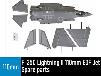
Freewing F-35C Lightning II 110mm EDF Jet Spare parts
All Spare Parts are available in stock.
1. Send email to us,our e-mail is [email protected]
we will reply message within 24 hours.
2.Live Chat Online in the following,
This Product is available in stock,we will ship the package box within 48 hours after the buyers pay money via paypal.
Spare parts For Freewing F-35C Lightning II 110mm EDF Jet Spare parts
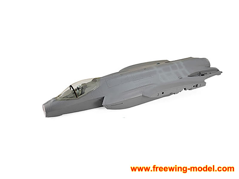
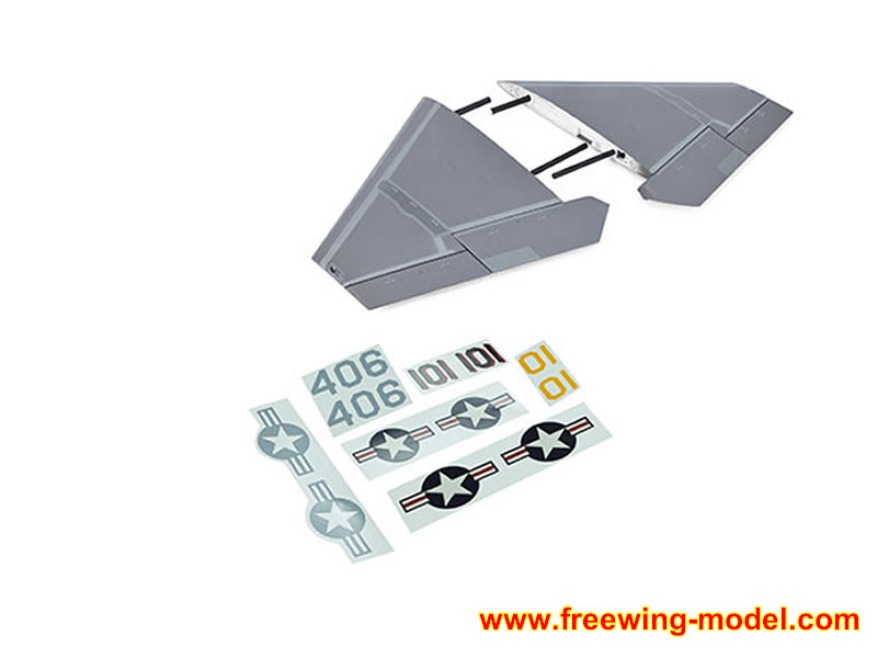
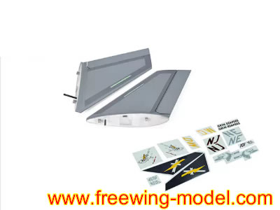
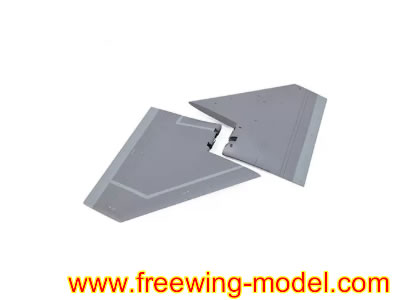
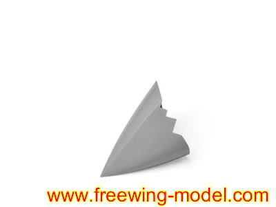
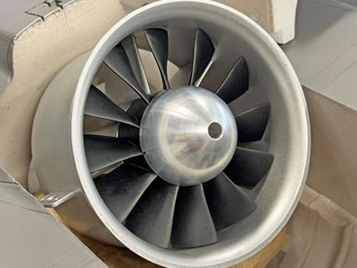
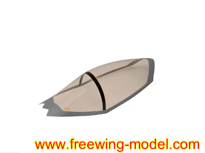
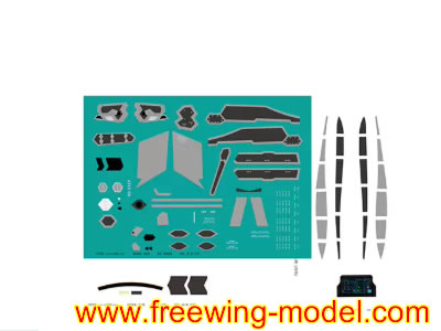
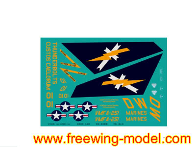
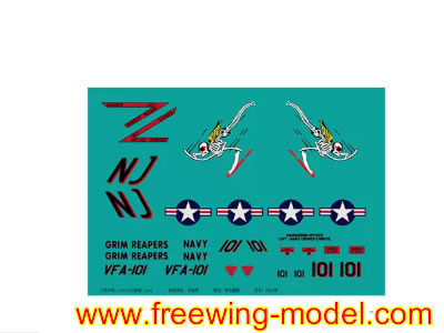
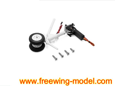
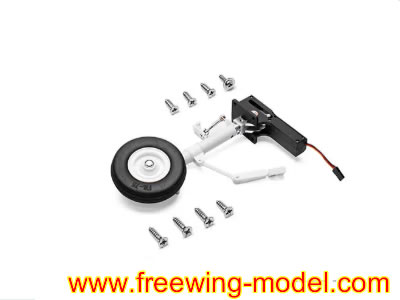
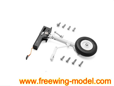
All Spare Parts are available in stock.
1. Send email to us,our e-mail is [email protected]
we will reply message within 24 hours.
2.Live Chat Online in the following,
Stage 1: Horizontal stabilizer (Elevator) installation (tail first)
- Align the plastic adapter lugs on each left/right horizontal stabilizer into the pivot slots on the rear fuselage tail boom.
- Plug the elevator servo extension wire from each horizontal tail into the matching fuselage servo plug.
- Center the elevator surface perfectly, then secure the two side horizontal tail mounts with FA3��8 mm machine screws (4 total). Do not over tighten; over torque will strip EPO foam threads.
- Check free elevator travel: full up/down motion without binding or cable snagging. Secure loose wiring with zip ties inside the fuselage tail cavity.
Stage 2: Twin canted vertical stabilizers (Rudders) assembly
- Route vertical tail servo wires through the fuselage vertical fin mounting holes. Connect each rudder servo plug to the fuselage extension harness one by one.
- Seat each canted vertical fin fully down onto the fuselage rear mounting bosses.
- Fasten using 4�� FA3��8 mm screws to lock the vertical stabilizers in position.
- Manually test rudder left right movement; confirm wiring is not pinched between stabilizer and fuselage frame.
Stage 3: Main wing installation (QUICK II tool free plug and lock system, signature for this 110 mm F 35C)
- Slide the thick main carbon fiber spar fully through the fuselage wing root tunnel, spanning left to right wing sockets.
- Unlock the wing latch buttons on both fuselage sides (press the button down to release the lock mechanism).
- Plug the aileron flap servo plugs from each main wing into the corresponding fuselage harness connectors. Double check polarity (pin alignment) to avoid reversed servo operation.
- Slide left right main wing wing root lugs onto the carbon spar, push the wings flush against the fuselage shoulder.
- Release the latch buttons. The spring loaded latches will pop up and mechanically lock the wings firmly onto the airframe. Gently tug each wing to confirm zero play.
For long term static display: Optional set screws can be tightened for extra wing rigidity; leave loose for easy transport disassembly.
Stage 4: Nose section, cockpit canopy and intake duct fit up
- Fit the plastic cockpit tub/pilot detail piece into the forward fuselage cockpit cavity.
- Clip the clear canopy hatch onto the fuselage nose cockpit hinge points; confirm the canopy latches shut securely.
- Install the nose cone; ensure the intake air duct channel inside the nose perfectly aligns with the front inlet leading to the 110 mm EDF unit. Any gaps will reduce EDF thrust performance. Seal minor intake gaps with thin foam tape if there is air leakage.
Stage 5: Landing gear & sequenced gear door pre check (factory pre mounted electric retracts)
- Connect the landing gear harness plug to the main gyro/central electronics board inside the fuselage.
- Power the system on (via temporary battery) and cycle landing gear up/down on your radio transmitter.
- Verify the gear doors open first, struts extend, then doors close (scale sequenced operation). Adjust servo linkage set screws if doors bind, stay ajar or jam.
- Check nose gear steering movement matches your transmitter rudder input.
Stage 6: LED & afterburner light wiring connection
- Locate the navigation light plug (wing/fuselage formation lights) and afterburner LED plug (exhaust nozzle) inside the rear fuselage.
- Plug both into the dedicated LED port on the Freewing EG01 6 axis gyro unit.
- Test: Navigation lights turn on when the radio system powers up; the afterburner LED illuminates under high throttle input (factory pre programmed).
Stage 7: Radio system wiring, gyro setup and transmitter binding
- Plug these components into the EG01 gyro input ports:
- ESC signal wire
- Aileron, elevator, rudder servo main harness lead
- Landing gear servo harness
- LED lighting harness
- Bind your 2.4 GHz receiver to your radio transmitter, then plug the receiver into the gyro��s receiver input port.
- Gyro baseline setup (critical for this large jet):
- Place the jet on a perfectly flat, level surface, keep the aircraft stationary.
- Power on the radio first, then plug in the 12S flight battery to power the jet.
- Hold the trim sliders neutral while the gyro auto calibrates (LED flashes solid once calibration finishes).
- Set gyro gain on your transmitter (start at 50 60% for maiden flight; increase for smoother high speed flight, reduce if the jet oscillates/wobbles).
Freewing F-35C Lightning II Super Scale 110mm EDF PNP Jet
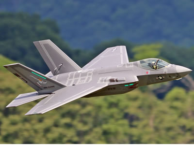
Freewing F-35C Lightning II 12S 110mm ARF Plus jet
Stage 8: Battery installation & Center of Gravity (CG) tuning (most critical flight step)
- Open the top fuselage battery hatch behind the cockpit. Secure the 12S Li Po battery using hook and loop tape on the battery tray.
- Official CG datum for the Freewing 110 mm F 35C: 110�C115 mm back from the leading edge of the main wing root (fuselage wing shoulder).
- Move the battery forward if the nose pitches up (tail heavy, unstable).
- Shift the battery rearward if the nose dives sharply (nose heavy, sluggish turns).
- Once CG is correct, secure excess battery power wiring with zip ties to prevent loose wires from hitting the 110 mm EDF fan.
Stage 9: Final pre flight control surface check
- Double check all control surface directions:
- Aileron: Right stick right next right aileron dips down
- Elevator: Right stick back next elevator deflects upward
- Rudder: Left stick left next vertical tail rudder moves left
- Reverse servo direction in your radio menu if any surface moves backwards.
- Cycle landing gear, test flaps, check all wiring is clear of moving parts and the EDF inlet/exhaust.
- Inspect the 110 mm EDF fan; ensure zero debris inside the fan shroud before the maiden flight.
Quick assembly order recap (field setup version for flying field fast build up)
- Attach horizontal tails . 2. Attach vertical stabilizers . 3. Install carbon spar + lock on main wings next 4. Plug in all servo/LED plugs next 5. Mount battery next 6. CG balance next 7. Gyro recalibrate next 8. Pre flight check next Fly

Freewing K-8 Karakorum 80mm EDF PNP Jet
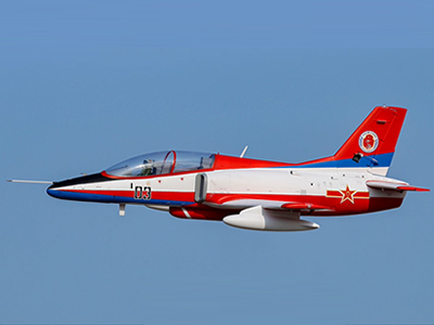
Freewing K-8 Karakorum 70mm EDF PNP Jet
3.Freewing F-35 110mm EDF jet
Freewing F-35C 110mm EDF Lightning II Super Scale Jet with Gyro RC Airplane

