
Home >>RC Airplane DIY Technology Article
How to assembly Freewing K-8 Karakorum 80mm 70mm EDF PNP Jet Step by step
Freewing K-8 Karakorum (70mm / 80mm EDF) PNP Step-by-Step Assembly Guide
Important Note: PNP version comes pre-installed with all servos, EDF unit, ESC, retracts, LED lights, wiring harness & integrated junction board. No motor/EDF assembly required. You only assemble airframe parts, install receiver, radio setup & balance. Differences between 70mm & 80mm: Only power system (70mm 80A ESC; 80mm 100A ESC). Assembly steps are identical.
Freewing K-8 Jet
K-8 Rear View
Pre-Requirements & Tools
Parts NOT included (Must Prepare)
- 7+ channel Radio Transmitter + Receiver
- 6S LiPo Battery
- 70mm: 3300�C5000mAh 35C 6S
- 80mm: 4000�C5000mAh 35C 6S
- LiPo balance charger
Small Tools
- Phillips screwdriver (supplied in kit)
- Foam safe tape / masking tape
- Thin foam CA glue (for optional scale parts)
- Cable ties
Step 1: Unbox & Inventory Check
- Lay out all parts on soft mat to avoid scratching EPO foam
- Verify components:
- Main fuselage (all electronics pre-wired)
- Left / Right main wings (quick-release type)
- Horizontal stabilizers (Left/Right)
- Vertical fin + Rudder
- Cockpit canopy
- Scale accessories: pitot tube, antenna, pylons, drop tanks
- Screw packet
- Visually inspect all control surfaces, retract landing gear, LED wiring for shipping damage.
?? Do NOT plug any battery in before full assembly.
Step 2: Install Horizontal Stabilizers (Elevators)
- Carefully feed the 2 servo extension cables from each horizontal stab through the fuselage tail slots.
- Slide left & right horizontal stabilizers fully into the fuselage tail sockets.
- Connect the JST servo plugs to the matching ports on fuselage integrated junction board. Match labels: Left Elevator / Right Elevator.
- Secure horizontal stabilizers using 4 supplied screws (2 each side). Do not over-tighten to avoid crushing foam.
- Manually move elevators to confirm no binding.
Step 3: Install Vertical Fin & Rudder
- Route rudder servo wire through vertical fin root.
- Insert vertical fin into fuselage rear slot, align flush.
- Plug rudder servo lead into junction board port marked Rudder.
- Fasten vertical stabilizer with mounting screws.
- Check free rudder travel by hand.
Step 4: Install Main Wings (Quick-Release System)
Freewing 2nd generation tool-free quick lock wings
- Locate the locking buttons on fuselage wing roots. Press button fully down and release �� button pops up = UNLOCK state.
- Align each wing��s multi-pin power/servo connector with fuselage wing root plug.
- Slide wing fully inward until seated; ensure connector clicks into place.
- Press the lock button down again and release. If button stays sunk = LOCKED.
? Pull wing gently outward to test lock; if it slides out, repeat locking procedure.
- Repeat for opposite wing.
?? If connectors resist plugging, check pin alignment �C NEVER force.
Step 5: Install Scale External Accessories
- Pitot tube: Insert into nose front hole; use tiny drop of foam CA if loose. Can be removed for transport.
- Fuselage top/bottom antennas: push into mounting holes (removable).
- Optional wing pylons + drop tanks: push-fit mount on wing hardpoints; glue lightly if desired.
- Fit cockpit canopy onto fuselage cockpit frame (magnetic / clip-on).
Step 6: Receiver Wiring (Critical Step)
All aircraft wiring terminates at the factory pre-installed integrated junction board inside fuselage behind cockpit.
- Open cockpit hatch, locate junction board.
- Plug your receiver servo cable into the board��s Receiver Input port.
- Route receiver antenna(s) outside fuselage:
- Run antennas out canopy gap or dedicated antenna slots
- Separate antennas 90��, keep away from ESC power wires to avoid interference
- Optional: If using Freewing Flight Guardian gyro, install between junction board and receiver.
Factory wiring already includes power for all servos, retracts, LED lights. No extra BEC needed.
Step 7: Pre-power Hardware Inspection (NO BATTERY YET)
Manually test every moving part:
- Ailerons, elevators, rudder, flaps: full travel, zero binding
- Electric retracts: cycle up/down by gently pushing gear legs (confirm no mechanical jam) Check all wiring plugs are fully seated. You can add a tiny amount of removable thread locker on loose plugs (recommended).
Step 8: First Power-On & Radio Configuration
- Turn ON your radio transmitter FIRST.
- Insert fully charged 6S LiPo into battery bay; secure battery with supplied hook-and-loop straps.
- Wait 2 seconds for ESC initialization tone sequence.
Radio Channel Mapping (7 Channels Minimum)
- CH1: Aileron
- CH2: Elevator
- CH3: Throttle (EDF Fan)
- CH4: Rudder / Nose Wheel Steering
- CH5: Landing Gear Up/Down
- CH6: Flaps
- CH7: Navigation LED Lights
Servo Neutral & Travel Adjustment
- Set all transmitter trims to center.
- Check all control surfaces are neutral (aligned with wing/tail).
- Adjust servo linkages if surfaces are offset. Recommended control throws (start for maiden flight):
- Aileron: 12mm low rate / 18mm high rate
- Elevator: 10mm low /16mm high
- Rudder: 22mm
- Flaps: 25�C30mm down (takeoff/landing)
?? Test throttle slowly! Do NOT run EDF at high power with people in front of intake/exhaust.
Step 9: Center of Gravity (CG Balance �C MAIDEN FLIGHT MUST!)
Official Freewing K-8 CG Position:
70mm / 80mm version: 72 mm back from main wing leading edge, measured at wing root fuselage centerline (with battery installed).
How to balance:
- Place fingertips under fuselage at CG mark
- Adjust battery forward/back inside battery compartment until plane sits level, nose slightly heavy (slightly forward CG safer for first flight)
- Secure battery firmly once ideal position found. Never fly with loose battery.
Step 10: Final Pre-Flight Checklist
- All wing/tail screws tight; wings fully locked
- Control surfaces respond correctly to transmitter (reverse servos if direction wrong)
- Retracts cycle reliably from radio switch
- LED lights turn on/off via assigned channel
- Battery secured, CG verified
- All wiring clear of control surfaces
- Throttle test: verify fan spins correct rotation
Common Troubleshooting Tips
- Wing connection loss: Clean multi-pin connectors with contact spray; ensure full seating
- Retracts do not move: Check junction board retract plug; verify sufficient LiPo voltage
- Servo jitter: Separate receiver antennas from high-current ESC cables
- EDF no spin: Check ESC power plug; listen for ESC startup beeps
- Loose scale parts: Use foam-safe CA only; avoid regular superglue which melts EPO
Transport Tip
For transportation: Remove pitot tube, antennas, unlock and detach both main wings to save space. Horizontal / vertical tails can stay installed.
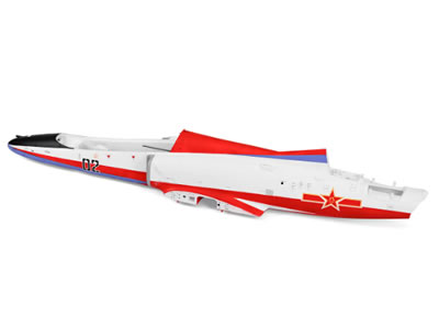
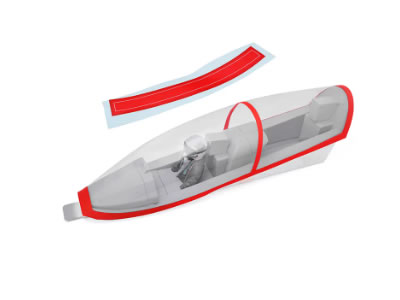
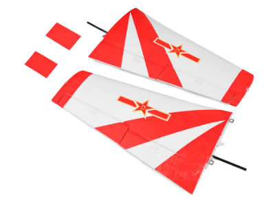
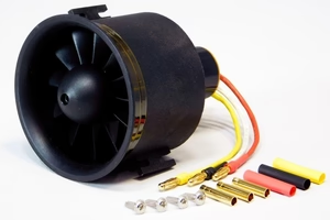
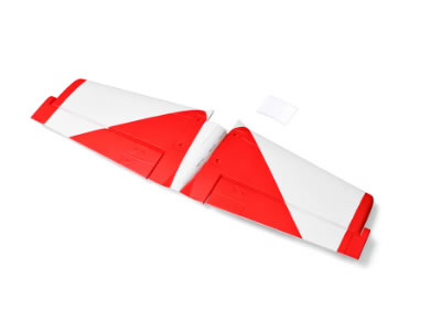
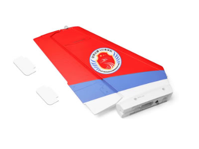
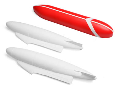
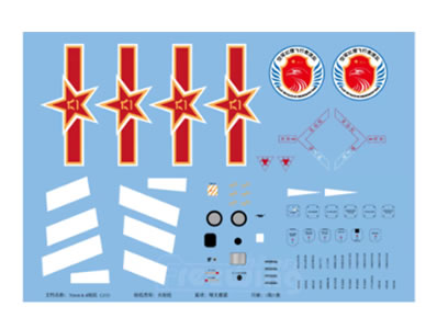
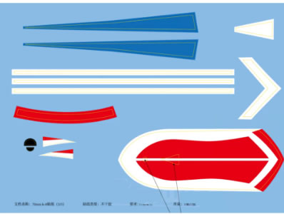
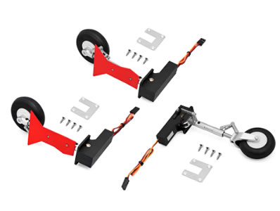
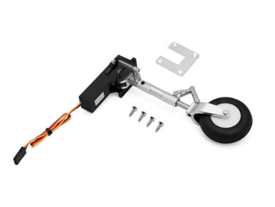
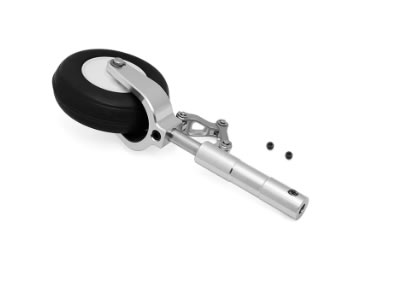
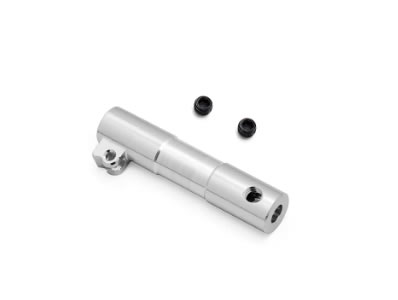
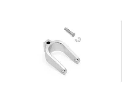
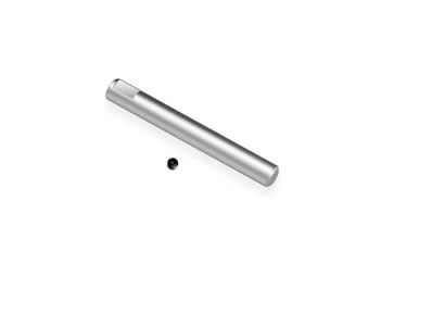
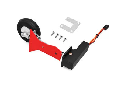
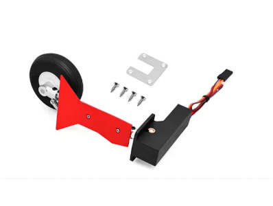
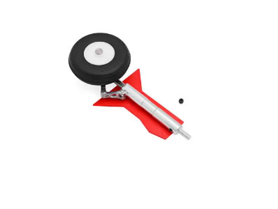
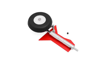
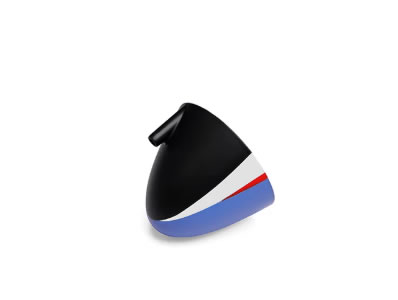
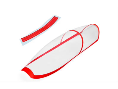
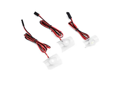
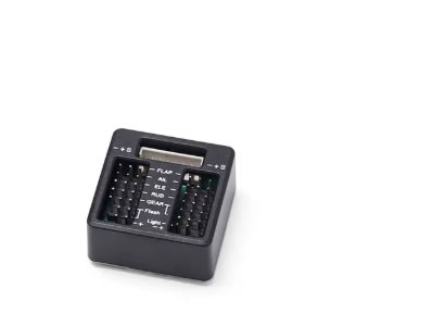
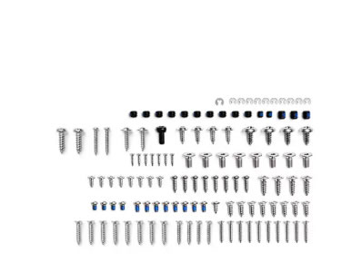
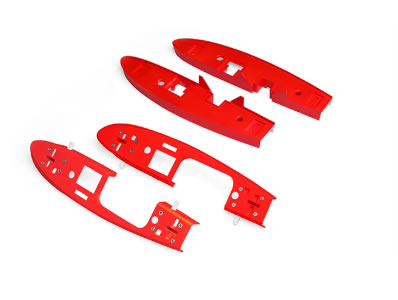
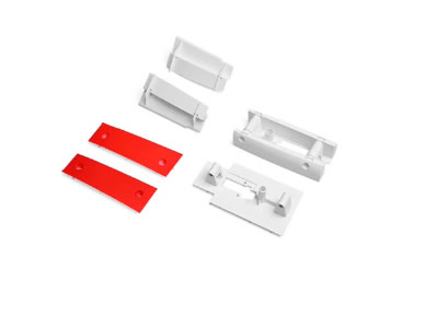
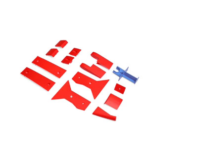
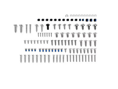
Freewing JL-8 K8 Karakorum 70mm 80mm EDF JET Spare parts


3.Freewing F-35 110mm EDF jet
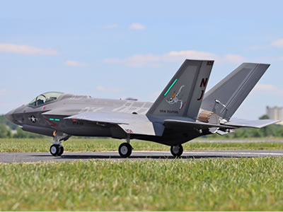
Freewing F-35C 110mm EDF Lightning II Super Scale Jet with Gyro RC Airplane

