Home >>RC Airplane DIY Technology Article
How to assembly freewing zeus45 turbine jet Step by step step by step RC Aircraft
The Zeus 45NT is a turbine-ready sport jet (1200mm span) pre-fitted with servos, landing gear, fuel tanks & heat insulation; you only need to install a turbine engine (KingTech K45/Xicoy X45/X60 recommended) and electronics
Pre-Assembly Preparation
Required Parts & Tools
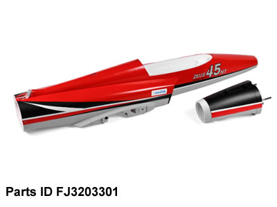
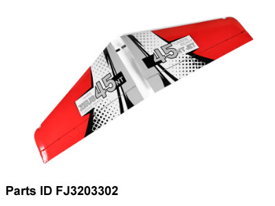
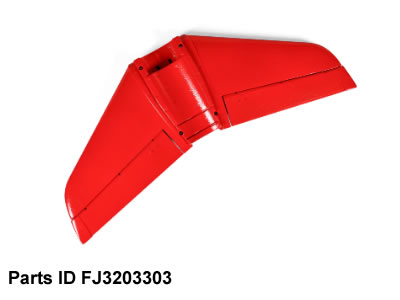
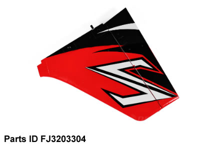
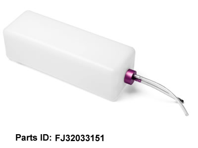
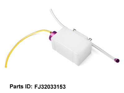
- Included factory parts: Split fuselage, main wings, horizontal/vertical stabilizers, pre-installed servos, electric landing gear with brakes, 1150cc main fuel tank + 150cc anti-bubble header tank, pre-routed fuel lines, insulated stainless tailpipe, engine mounting bulkhead
- Extra components you must prepare:
- Turbine engine (K45/X45/X60, matched mounting bracket)
- Turbine ECU + fuel pump + ignition system
- 6+ channel RC transmitter/receiver, flight gyro
- Dual power supply: 2S LiPo (7.4V) for servos/gear/brakes; separate battery for turbine ECU
- Fuel: Jet A1 / kerosene + turbine oil
- Tools: Phillips screwdrivers (M3), hobby knife, zip ties, heat-shrink tubing, thread locker (blue Loctite), digital CG balance scale
Pre-Check All Components
- Cross-check parts against the official spare parts list to confirm no missing brackets, screws, pipe fittings.
- Inspect fuselage heat shielding around the turbine bay (critical to prevent EPO foam melting).
- Test landing gear & brake servos manually to ensure free movement before installation.
Step 1: Install Exhaust Tailpipe (First Critical Step)
The tailpipe installs before joining front/rear fuselage halves Freewing-m... :
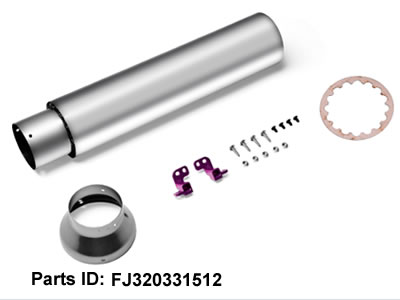
- Slide the insulated dual-wall stainless tail nozzle into the rear fuselage tail section from the front opening.
- Secure the tailpipe fixing bracket (Part A) using TM3��5mm screw + M3 nut, lock loosely first for alignment adjustment.
- Align the tailpipe centerline perfectly parallel to the fuselage central axis (misalignment causes overheating & thrust loss).
- Tighten tailpipe fasteners completely after alignment.
Step 2: Join Front & Rear Fuselage
This jet uses glue-free split fuselage design for easy transport:
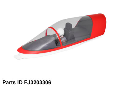
- Mate the front fuselage (cockpit/equipment bay) and rear fuselage (turbine/tail section) precisely along the locating pins.
- Insert the fuselage connecting bolts from the bottom and tighten evenly (do not over-tighten to avoid cracking EPO foam).
- Recheck tailpipe position once fuselage is joined to confirm no pipe shift.
Step 3: Mount Turbine Engine
- Install the dedicated engine bulkhead into the fuselage turbine bay (pre-cut for K45/X45 engines). Secure the bulkhead with PWA3��12 screws.
- Mount your turbine onto its custom locking bracket, slide the engine into the bay, connect the turbine exhaust outlet tightly to the front end of the installed tailpipe (use high-temperature silicone sealant at the joint to stop hot gas leakage).
- Lock the engine fixing clips into place, lightly torque all engine mounting screws with blue thread locker to prevent loosening from vibration.
- Leave 3�C5mm gap between turbine casing and fuselage foam for heat dissipation.
Step 4: Plumb Fuel System (Pre-installed tanks, only connect lines)
The Zeus 45NT comes with factory-plumbed fuel tanks inside the fuselage:
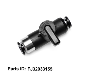
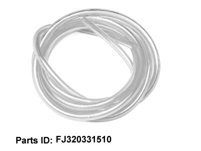
- Route fuel lines: Main tank �� bubble header tank �� turbine fuel pump �� turbine fuel inlet. Cut silicone fuel tubing to custom length, use hose clamps on all joints to prevent air bubbles/fuel leaks.
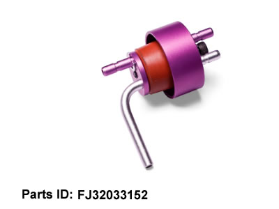
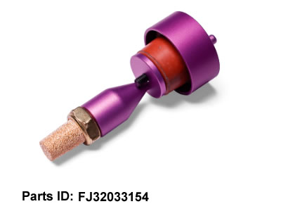
- Connect the tank vent tube to the fuselage external vent port; install the vent plug when parking the jet to avoid fuel spillage.
- Mount the turbine fuel pump onto the pre-provided wooden pump bracket inside the equipment bay, fix with double-sided foam tape + zip ties to reduce vibration.
- Perform a fuel leak test: Pressurize the tank gently, check every joint for seepage before powering the turbine.
Step 5: Assemble Tail Stabilizers
- Attach the horizontal stabilizer onto the rear fuselage mounting pins, secure with hidden screws from underneath.
- Install vertical stabilizer onto the fuselage upper rear socket, lock the built-in hinge fastener.
- Connect elevator/rudder control linkages to factory pre-installed tail servos:
- Set servo horns to neutral (servo centered via transmitter first).
- Adjust linkage length so elevator/rudder sit perfectly level at neutral radio position.
- Secure linkage clevises with small retaining pins to avoid falling off in flight.
- Use a right-angle ruler to verify horizontal tail ? vertical fin form a perfect 90�� angle.
Step 6: Install Main Wings (Quick-Screwless Quick-Release Wings)
- Insert the left & right wing carbon spars into the fuselage wing sockets fully until seated.
- Lock the wing quick-release latches on both sides of the fuselage (no screws required for field assembly). Shake the wings firmly to confirm no play or looseness.
- Connect the aileron servo extension wires from wings to the fuselage internal wiring harness via plug connectors.
- Adjust aileron linkages to set neutral aileron flat and equal up/down travel (��18�� recommended for sport flight).
Step 7: Electronics Wiring & Receiver Setup
Wiring Layout Rules (Avoid RF interference)
- Separate two independent power circuits to eliminate voltage interference:
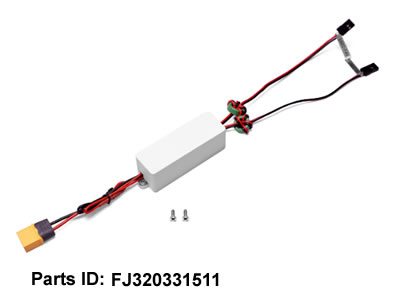
- Circuit 1 (2S 7.4V LiPo): Powers all flight servos, landing gear, brakes, navigation LEDs, onboard gyro. Fit a UBEC for stable 6V servo power Freewing-m... .
- Circuit 2 (separate LiPo): Exclusive power for turbine ECU & ignition system (never share this battery with flight servos).
- Mount receiver & gyro in the forward cockpit equipment bay (away from fuel pump/turbine to avoid RF noise). Route receiver antenna forward outside the fuselage.
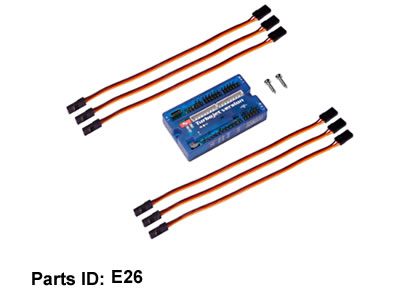
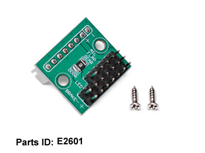
- Wiring channel mapping on flight control board:
- RUD = Rudder��ELE = Elevator��AIL = Aileron��GEAR = Landing Gear��BRAKE = Brake channel
- Bind receiver to your radio transmitter, then complete servo reverse & travel adjustment in radio settings.
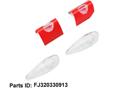
- Install navigation LEDs to the reserved wiring plugs on the fuselage nose/wings.
Step 8: Landing Gear & Brake Commissioning
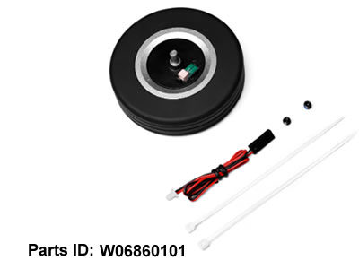
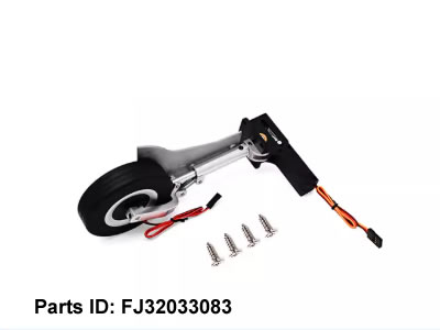
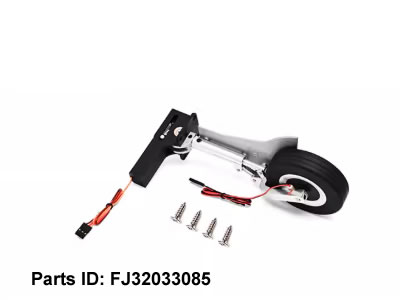
- All electric retractable landing gear is pre-installed inside fuselage wheel wells. Connect gear servo wire to the GEAR channel of the flight board.
- Link brake control wire to the brake channel, test brake function via transmitter: check brake clamping & release smoothly without jamming.
- Test retraction/extension repeatedly 10 times to confirm no gear binding; adjust wheel well doors if they catch the struts.
Step 9: Pre-Flight Calibration & CG Setting (Extremely Important)
1. Servo & Turbine Bench Test
- Power on radio system, check full movement of ailerons/elevator/rudder/gear/brakes, confirm no binding or reversed directions.
- Complete turbine ECU calibration per your turbine brand��s manual (priming pump, ignition test, idle setup). Never start the turbine indoors.
2. Center of Gravity (CG) Calibration
Official CG position: 85�C90mm back from the leading edge of the wing root
- Remove all fuel, place the jet on CG balancing stands at the specified position.
- Shift the 2S flight battery forward/back inside the nose battery compartment until the jet balances level (slight nose-down static balance is safer for turbine jets).
- Lock the flight battery with hook-and-loop straps + foam bracing to prevent battery shift during flight.
Step 10: Final Safety Inspection
- Re-tighten all engine, tailpipe, wing mounting screws with thread locker.
- Check all fuel lines again for leaks, secure loose wiring with zip ties.
- Confirm turbine heat shielding is intact, no foam exposed near hot exhaust components.
- Do a full range test of the RC system at 100m distance.
Field Assembly (5-Minute Quick Setup After Home Build)
- Lock both main wings onto fuselage latches.
- Plug wing servo connectors into fuselage harness.
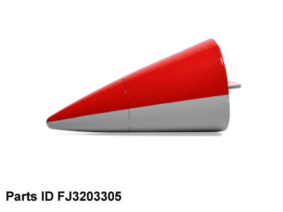
- Install nose cone, fill fuel tank, connect flight & turbine batteries.
- Check CG one last time, then perform turbine start sequence following turbine ECU instructions.
Critical Safety Warnings
- Keep flammable items at least 3m away during turbine startup; stand to the side of the exhaust (jet exhaust reaches 600C+).
- Never run the turbine without the tailpipe installed (will burn fuselage foam instantly).
- Always use dedicated turbine kerosene fuel; gasoline is forbidden.
- This is a high-speed turbine jet, only fly on paved runways with turbine jet flight experience.