
how to install radio controller Receiver for Freewing F-35C 110mm EDF Jet?
radio controller Receiver Installation Guide
This jet uses the built-in EG01 6-axis gyro hub board; you do NOT plug servos/ESC directly to the receiver. All servos, landing gear, EDF ESC, thrust reverse, lights connect to the Freewing gyro mainboard, and only the receiver plugs into the gyro board. Requirement: Minimum 7-channel receiver (7ch for thrust reverse; 8ch for gyro mode switch; 9ch for formation lights)Freewing-m...
1. Prep before wiring
- Power OFF transmitter, keep throttle stick at full low. Disconnect airplane LiPo batteries (2×6S 22.2V packs).
- Take off the cockpit canopy, open the electronics bay.
- Locate the EG01 gyro controller board inside the fuselage; it has one 3-pin servo-style input port for your receiver signal.
- Bind your receiver to your radio transmitter first (follow your radio brand binding manual: FrSky, Spektrum, Futaba etc).
2. Receiver wiring (Critical!)
✅ Only ONE signal cable runs from receiver → EG01 gyro board. The gyro board handles all servo/gear/EDF power distribution via its built-in 10A UBEC from the 130A ESC.
- Use a standard 3-pin servo extension wire:
- Signal (white/yellow): from receiver channel out → gyro board signal pin
- +5V (red): power
- GND (black/brown): ground
Double check pinout! Reversed 5V/GND will burn the gyro board. Match the silk print on EG01 board: SIG / + / GND.
- Receiver channel assignment (standard mapping for this F-35C):
Receiver Ch Function CH1 Aileron CH2 Elevator CH3 Throttle / EDF CH4 Rudder CH5 Landing Gear CH6 Flaps CH7 Thrust Reverser CH8 Gyro Mode ON/OFF CH9 Formation Lights
All these functions are routed inside the EG01 gyro; you set channel mapping/reversing in your radio, NOT by swapping servo plugs.
3. Mount the receiver
- Stick receiver with thin double-sided foam tape inside the forward fuselage electronics bay, away from ESC, EDF motor, battery wires (avoid electrical interference).
- Antenna placement:
- Spread antennas at 90° angle.
- Route antennas away from carbon tubes and high-current power cables.
- Do NOT coil antennas; keep them straight inside the fuselage cavity.
- Secure loose wires with cable ties, leave small slack so canopy closes without pinching wires.
4. Radio setup & gyro configuration
- Turn on your transmitter first, throttle stick all the way down.
- Connect the 2×6S LiPo batteries to the jet.
- Wait for EG01 gyro finish initialization (LED solid after blinking). Do NOT touch control sticks during gyro boot.
- Test all surfaces slowly:
- Aileron, elevator, rudder direction check. Reverse channels in your radio if movement is backwards.
- Test gear up/down, flaps, thrust reverser, light switch.
- Gyro test: Tilt the airframe, gyro should oppose movement. Adjust gyro gain on your radio CH8 switch as needed.
- Set throttle cut / failsafe on your radio! On signal loss, failsafe must set throttle to zero.
5. Final safety inspection
- Unplug batteries, recheck all connectors, no pinched wires.
- Check center of gravity (CG) per Freewing manual before first flight.
- Range test your radio system per your transmitter manual.
Common Mistakes to Avoid
- ❌ Don’t plug servos directly into receiver. This plane uses a central gyro hub.
- ❌ Reversing the 3-pin signal plug (red/black swap) will destroy the EG01 gyro.
- ❌ Powering on plane BEFORE transmitter (can cause runaway EDF).
- ❌ Skipping failsafe setup: very dangerous for this large 110mm 12S jet.
- ❌ Mounting receiver next to high-current power wires → radio glitch.
Video reference for this jet install
If you tell me your radio brand (Spektrum / FrSky / Futaba / Radiomaster) I can give you exact radio model setup and mixing for this F-35C.
今天 13:50
Spektrum
Freewing F-35C 110mm EG01 + Spektrum Setup
Important note: EG01 gyro is the flight controller here, NOT Spektrum AS3X. The Spektrum receiver only sends PPM/SBUS signal into EG01. All stabilization, servo/gear/EDF control is handled by Freewing EG01. Do NOT enable AS3X on your Spektrum receiver. Use an 8ch or larger Spektrum receiver (AR8020T, AR10100T etc.)
1. Wiring to EG01
EG01 has one 3-pin input port for your Spektrum receiver signal:
- Use a 3-pin servo wire from receiver to EG01 SIG / +5V / GND
- If your Spektrum receiver supports SBUS, use SBUS pin on receiver to EG01 SIG pin (recommended). If no SBUS, use PPM.
⚠️ Pinout check: SIG = signal, RED = +5V, BLACK = GND. Reverse power burns EG01.
2. Bind Spektrum receiver (SmartSafe)
- Throttle stick FULL LOW, all other sticks centered, switches in your default flight positions.
- Insert bind plug into receiver bind port, power receiver (power from EG01 5V).
- Power on transmitter while holding bind button. Wait receiver LED solid.
- Power off receiver, remove bind plug. Done binding.
SmartSafe automatically sets throttle failsafe to LOW at bind time, this is critical for this 12S jet.
3. Spektrum Channel Assign (Model Setup, NX / iX / DX)
Go to Channel Assign menu on your Spektrum radio, map as below:
| Ch | Function | Recommended Switch (Spektrum) |
|---|---|---|
| CH1 | Aileron | Right stick roll |
| CH2 | Elevator | Right stick pitch |
| CH3 | Throttle / EDF | Left stick throttle |
| CH4 | Rudder | Left stick yaw |
| CH5 | Landing Gear | Switch A |
| CH6 | Flaps | Switch B |
| CH7 | Thrust Reverse | Switch C |
| CH8 | EG01 Gyro Mode | Switch D (3-position switch preferred) |
| CH9 | Formation Lights | Switch E (optional) |
Radio setup steps (NX / iX series)
- Create a new airplane model, select Airplane > Normal (no AS3X/SAFE)
- Channel Assign: assign each source to channels as above
- Servo Reverse: test after powering EG01. Reverse channels in radio if surfaces move wrong direction.
- Travel/Endpoints: start at 100%, adjust after first ground test; Freewing factory setup usually works at 100%.
- Subtrim: set all surfaces neutral with EG01 powered on, do not adjust subtrim while EG01 is booting.
4. EG01 Gyro Mode on CH8
EG01 uses CH8 signal level to switch gyro modes:
- Low position (-100%): Gyro OFF
- Mid position (0%): Gyro Normal / Medium gain
- High position (+100%): Gyro High gain
Use a 3-position switch for CH8 on your Spektrum radio for 3 modes. If you use 2-position switch, you only get Gyro ON/OFF. Gyro gain tuning: adjust in Freewing Assistant APP via Bluetooth, NOT inside Spektrum radio.
5. Failsafe Check (Very Important for 110mm F-35C)
Spektrum SmartSafe:
- On signal loss: Throttle channel goes to the LOW position you set during binding.
- Other channels hold last position. ✅ Ground test failsafe: secure jet, battery connected, radio on. Turn transmitter OFF. EDF must immediately shut down.
If throttle does NOT cut, rebind with throttle all the way down.
6. Power-on / Gyro Boot Sequence (DO NOT SKIP)
- Turn Spektrum transmitter ON first, throttle stick full low, CH8 switch to Gyro OFF for initial test.
- Connect the 2×6S batteries to jet.
- Leave jet completely still, do not touch airframe or sticks while EG01 boots (LED blinks, then solid when ready).
- After LED solid: test all surfaces, gear, flaps, thrust reverse.
- Verify gyro function: switch CH8 to gyro on, gently tilt jet; control surfaces should oppose the tilt.
7. Receiver Mount & Antenna for Spektrum
- Mount receiver with thin foam tape in forward electronics bay, away from ESC, battery power wires.
- Two antennas: route at ~90°, avoid carbon fiber and high-current cables. Do not coil antennas.
- Secure wires with zip ties with slack for canopy closing.
8. Pre-flight checklist
- Radio range test (Spektrum Range Test function)
- Control direction check
- Gear up/down, flaps, thrust reverse test
- Gyro mode switching test
- Failsafe throttle cut test
- CG check per Freewing manual before maiden flight
Common Spektrum + EG01 Mistakes
❌ Turning transmitter on AFTER battery → EG01 may boot with wrong stick positions ❌ Enabling AS3X/SAFE on Spektrum receiver: dual gyro conflict, unstable flight ❌ Binding with throttle stick not all the way down → failsafe will NOT kill EDF on signal loss ❌ Reversed SIG/5V/GND plug → burn EG01 board ❌ Moving aircraft while EG01 is booting → gyro zero offset wrong
What Spektrum transmitter do you have? (NX6/NX8, iX12, DX etc.) I can give exact menu path for your radio.
今天 13:51
FrSky
Freewing F-35C 110mm EG01 + FrSky Setup (Taranis / X9D / X10 / X12S / TX16S)
Core point: EG01 is the flight controller/gyro, your FrSky receiver only sends SBUS signal into EG01. All servos, gear, EDF, thrust reverse are controlled by EG01. Do NOT connect any servos directly to receiver. Recommended receiver: R-XSR, G-RX8, X8R, 8ch or higher, SBUS output (SBUS is strongly preferred over PPM for this jet).
1. Wiring EG01 ↔ FrSky receiver
EG01 has one 3-pin signal input port labeled SIG / +5V / GND
- Use standard 3-wire servo cable from receiver SBUS pin to EG01:
- White/Yellow = SIG (SBUS signal)
- Red = +5V
- Black/Brown = GND
⚠️ Polarity is critical. Reversed red/black will burn EG01 gyro board. EG01 gets its 5V power from the plane’s built-in ESC UBEC; the receiver is powered by this same 5V.
2. Bind FrSky receiver (D16 mode recommended)
- Transmitter OFF. Throttle stick FULL LOW, all switches in default flight positions.
- Put receiver into bind mode (hold receiver bind button while applying 5V power from EG01).
- Power on your FrSky radio, enter model setup → Internal RF → Bind (D16 mode, 8+ channels).
- Wait receiver LED solid = bind complete. Power off receiver, radio.
Use D16; D8 only supports max 8 channels and is older.
3. Channel Mapping (Taranis / OpenTX)
OpenTX default stick order is TAER (Throttle, Aileron, Elevator, Rudder). EG01 expects:
| Channel | Function | Radio control |
|---|---|---|
| CH1 | Aileron | Right stick horizontal |
| CH2 | Elevator | Right stick vertical |
| CH3 | Throttle / EDF | Left stick vertical |
| CH4 | Rudder | Left stick horizontal |
| CH5 | Landing Gear | Switch SA |
| CH6 | Flaps | Switch SB |
| CH7 | Thrust Reverse | Switch SC |
| CH8 | EG01 Gyro Mode | Switch SD (3-position switch best) |
| CH9 | Formation Lights | Switch SE (optional) |
OpenTX Model setup steps
- New model → Airplane.
- Go to Inputs page and confirm:
- Input1 Ail = Ail
- Input2 Ele = Ele
- Input3 Thr = Thr
- Input4 Rud = Rud
- Go to Mixers:
- CH1: Ail
- CH2: Ele
- CH3: Thr
- CH4: Rud
- CH5: SA
- CH6: SB
- CH7: SC
- CH8: SD
- CH9: SE
- Channel Reversal: Do NOT reverse channels in mixer page yet. Power up EG01, test surface movement. Reverse channels in OpenTX if surfaces move opposite to stick command.
- Travel/Weight: Start at 100%. Adjust after ground test.
EG01 Gyro modes on CH8
EG01 reads CH8 value to switch gyro:
- -100% = Gyro OFF
- 0% = Medium Gyro Gain
- +100% = High Gyro Gain Use a 3-position switch (SD) on your FrSky radio for all three modes. Gyro gain fine tuning is done inside Freewing Assistant Bluetooth APP, not in OpenTX.
4. Failsafe Setup (EXTREMELY IMPORTANT for 12S 110mm EDF)
After binding, you must set failsafe. If signal is lost, throttle must go to zero. Two options for FrSky:
Option A: OpenTX Custom Failsafe (best for ACCESS / newer radios)
- Model Setup → Internal RF → Failsafe → Custom
- Set each channel:
- CH3 (Throttle): -100% (zero throttle)
- All other channels: recommended neutral positions
- Save. Test: Power plane, radio ON then turn radio OFF. EDF must shut down immediately.
Option B: Receiver hardware F/S button (older D16 receivers like R-XSR / X8R)
- Radio ON, plane powered, throttle all the way down, all switches set to failsafe positions.
- Short press the F/S button on receiver. Receiver LED flashes twice = saved.
Rebinding will erase failsafe, you must re-set after every re-bind.
❌ Never use “No Pulse” failsafe with EG01, it can cause unpredictable behaviour.
5. Receiver mounting & antenna routing
- Mount receiver with thin foam tape in forward electronics bay. Keep away from ESC, battery high-current wires.
- Route antennas at roughly 90° to each other.
- Keep antennas away from carbon fiber structures and power cables, do not coil antennas.
- Secure wires with zip ties with enough slack so canopy closes without pinching wires.
6. Power-up & EG01 gyro boot sequence (follow strictly)
- Turn FrSky transmitter ON first, throttle stick full low, CH8 switch set to Gyro OFF for initial test.
- Connect the two 6S LiPo batteries to the jet.
- Do NOT touch or move the aircraft while EG01 boots. Leave it completely still until LED stops blinking and becomes solid.
- After solid LED: test aileron, elevator, rudder, gear, flaps, thrust reverse.
- Switch CH8 to gyro ON, gently tilt airframe: surfaces should oppose the tilt. This confirms gyro works.
7. Pre-flight checklist
- Radio range test (OpenTX range test function)
- Check direction of all control surfaces
- Gear up/down, flaps, thrust reverse, light test
- Failsafe test (radio off, throttle cuts)
- CG check following Freewing manual before maiden flight
Common FrSky + EG01 mistakes
❌ Binding in D8 mode and trying to use 9 channels ❌ Servos plugged directly into receiver ❌ Powering plane before turning on transmitter → EG01 boots with wrong stick offsets ❌ No failsafe set → runaway EDF risk ❌ Reversed SIG/5V/GND pin → burn EG01 ❌ Moving plane during EG01 boot → gyro offset wrong, unstable flight
What FrSky radio are you using? (TX16S, X9D+, X10, X12S etc.) I can give exact menu paths for your radio.
今天 13:53
Futaba
Freewing F-35C 110mm EG01 + Futaba Setup (T10J / T14SG / T16IZ / T32MZ)
Core: EG01 is the flight controller / 6-axis gyro. Futaba receiver only sends S.BUS signal to EG01. All servos, landing gear, EDF, thrust reverse are connected to EG01 board. Do NOT plug servos directly into Futaba receiver. Recommended receiver: R7206SB / R7306SB / R6303SBE (S.BUS capable, ≥8ch). Use T-FHSS or FASSTest. S.BUS is mandatory for this setup.
1. Wiring EG01 ↔ Futaba receiver
EG01 has one 3-pin input port marked SIG / +5V / GND
- 3-wire servo cable: Futaba receiver S.BUS port → EG01
- White/Yellow = SIG (S.BUS signal)
- Red = +5V
- Black/Brown = GND
⚠️ Polarity is critical. Swap red/black and you will burn the EG01 gyro board. Receiver 5V power comes from the plane’s ESC built-in UBEC via EG01.
2. Receiver Linking (Binding)
- Transmitter OFF. Throttle stick full low, all switches in your default flight positions.
- Hold the receiver LINK button, apply 5V power from EG01. Receiver LED flashes.
- Power Futaba transmitter, enter Link menu, start linking (T-FHSS / FASSTest multi-channel mode).
- Receiver LED solid = link complete. Power off plane, release link button.
3. Futaba Channel Assignment (Important, EG01 expects this order)
| Channel | Function | Futaba Switch / Stick |
|---|---|---|
| CH1 | Aileron | Right stick roll |
| CH2 | Elevator | Right stick pitch |
| CH3 | Throttle / EDF | Left stick throttle |
| CH4 | Rudder | Left stick yaw |
| CH5 | Landing Gear | SW-A |
| CH6 | Flaps | SW-B |
| CH7 | Thrust Reverse | SW-C |
| CH8 | EG01 Gyro Mode | SW-D (3-position switch preferred) |
| CH9 | Formation Lights | SW-E (optional) |
Futaba Radio Model Setup
- New model → Airplane (Normal, no built-in gyro mixing).
- Go to Function Menu / Channel Assign and map each control source as in table above.
- Servo Reverse: Do NOT reverse channels before powering EG01. Power up, test surface movement. Reverse channels in the Futaba radio if surfaces move opposite to stick command.
- Travel: Start at 100%. Adjust after ground test.
EG01 gyro modes via CH8:
- -100% = Gyro OFF
- 0% = Medium gain
- +100% = High gain Gyro gain fine tuning is done in Freewing Assistant Bluetooth APP, not in Futaba radio.
4. Failsafe Setup (Critical for 12S 110mm EDF jet)
Futaba S.BUS receivers support F/S preset positions.
- Go to Model Menu → Failsafe
- Set:
- CH3 (Throttle): F/S, set stick fully low
- CH1,CH2,CH4: NOR (hold last position)
- CH5,CH6,CH7,CH8: NOR or neutral positions
- Save. ✅ Ground test: plane powered, radio ON. Turn transmitter OFF. EDF motor must immediately shut down.
If throttle does not cut: re-set failsafe and re-test. Never skip this step.
5. Receiver Mount & Antennas
- Mount receiver with thin foam tape in forward electronics bay. Keep away from ESC, battery high-current wires.
- Route antennas at roughly 90° to each other.
- Keep antennas away from carbon fiber fuselage and high-current power cables, do not coil antennas.
- Secure wires with zip ties, leave slack so canopy closes without pinching wires.
6. Power-up & EG01 Gyro Boot Sequence (Follow strictly)
- Turn Futaba transmitter ON first, throttle stick full low, CH8 switch set to Gyro OFF for initial test.
- Connect the two 6S LiPo batteries to the jet.
- Leave the plane completely still during gyro initialization. Do not touch the airframe or sticks. Wait until EG01 LED stops blinking and stays solid.
- After solid LED: test aileron, elevator, rudder, gear, flaps, thrust reverse.
- Switch CH8 to gyro ON, gently tilt airframe: control surfaces should oppose the tilt. This confirms gyro works.
7. Pre-flight checklist
- Radio range test (Futaba Range Check function)
- Verify direction of all control surfaces
- Gear up/down, flaps, thrust reverse, lights test
- Failsafe test (radio OFF → throttle cuts)
- CG check following Freewing manual before maiden flight
Common Futaba + EG01 Mistakes
❌ Using S-FHSS 6ch only receiver (not enough channels) ❌ Servos plugged directly into receiver ❌ Powering plane BEFORE transmitter → EG01 boots with wrong stick offsets ❌ Failsafe set to NOR (hold last position) on throttle channel → runaway EDF risk ❌ Reversed SIG/5V/GND pin → burn EG01 ❌ Moving aircraft during EG01 boot → gyro zero offset wrong, unstable flight
What Futaba transmitter do you have? (T10J / T14SG / T16IZ / T32MZ) I can give exact menu path for your radio.
Want me to summarize all three radio brands (Spektrum / FrSky / Futaba) into one quick reference table for this F-35C?
How to Choose correct Lipo battery for Freewing f-35C 110mm edf jet?
how to install radio controller Receiver for Freewing F-35C 110mm EDF Jet ?
How to assemble Freewing F35C 110mm EDF Jet step by step in 2026?
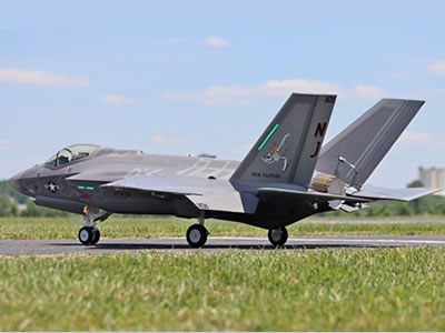
Freewing F-35C Lightning II Super Scale 110mm EDF PNP Jet
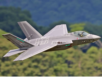
Freewing F-35C Lightning II 12S 110mm ARF Plus jet
radiomaster
Freewing F-35C 110mm EG01 + RadioMaster (EdgeTX / OpenTX, TX16S / Boxer / TX12 / Zorro)
Key point: EG01 is the 6-axis flight gyro. RadioMaster receiver only sends SBUS signal into EG01. All servos, gear, EDF, thrust reverse connect to EG01. Do NOT plug any servos directly into receiver. Recommended receiver: RadioMaster ER8 / ER16, R81, R168 (ELRS SBUS output, ≥8 channels). ELRS is preferred for RadioMaster.
1. Wiring EG01 ↔ RadioMaster receiver
EG01 input port marked SIG / +5V / GND Use standard 3-wire servo cable from receiver SBUS pin to EG01:
- White/Yellow = SIG (SBUS signal)
- Red = +5V
- Black/Brown = GND ⚠️ Polarity is critical. Reversed red/black will burn EG01 gyro. The receiver gets 5V power from the plane’s ESC built-in UBEC via EG01.
2. Bind ELRS receiver (RadioMaster)
- Transmitter OFF. Throttle stick fully down, all switches at default flight positions.
- Put receiver into bind mode: hold bind button while applying 5V power from EG01.
- On RadioMaster: Model Setup → Internal RF → ELRS → Bind.
- Receiver LED solid = bind complete. Power off aircraft.
3. Channel mapping (EdgeTX / OpenTX)
EG01 expects this channel order:
| Channel | Function | RadioMaster Switch / Stick |
|---|---|---|
| CH1 | Aileron | Right stick roll |
| CH2 | Elevator | Right stick pitch |
| CH3 | Throttle / EDF | Left stick throttle |
| CH4 | Rudder | Left stick yaw |
| CH5 | Landing Gear | SA |
| CH6 | Flaps | SB |
| CH7 | Thrust Reverse | SC |
| CH8 | EG01 Gyro Mode | SD (3-position switch recommended) |
| CH9 | Formation Lights | SE (optional) |
EdgeTX Model Setup Steps
- New model → Airplane.
- Go to Inputs
- Input1 Ail = Ail
- Input2 Ele = Ele
- Input3 Thr = Thr
- Input4 Rud = Rud
- Go to Mixers
- CH1: Ail
- CH2: Ele
- CH3: Thr
- CH4: Rud
- CH5: SA
- CH6: SB
- CH7: SC
- CH8: SD
- CH9: SE
- Channel Reversal: Do NOT reverse channels before powering EG01. Power up, test surface movement. Reverse channels in EdgeTX if surfaces move opposite to stick command.
- Travel/Weight: Start at 100%. Adjust after ground test.
EG01 Gyro modes via CH8
EG01 reads CH8 value to switch gyro gain:
- -100% = Gyro OFF
- 0% = Medium Gyro Gain
- +100% = High Gyro Gain
This Product is available in stock,we will ship the package box within 48 hours after the buyers pay money via paypal.
Gyro gain fine tuning is done inside Freewing Assistant Bluetooth APP, not in EdgeTX. Use a 3-position switch (SD) for all three modes.
4. Failsafe Setup (CRITICAL for this 12S 110mm EDF jet)
Use Custom Failsafe in EdgeTX (ELRS):
- Model Setup → Internal RF → Failsafe → Custom
- Set each channel:
- CH3 (Throttle): -100% (zero throttle)
- CH1,CH2,CH4: neutral
- CH5,CH6,CH7,CH8: neutral positions
- Save settings. ✅ Ground test: Plane powered, radio ON, then turn OFF transmitter. EDF must shut down immediately.
❌ Never use "No Pulse" failsafe with EG01, it causes unpredictable behaviour.
5. Receiver Mount & Antennas
- Mount receiver with thin foam tape in forward electronics bay. Keep away from ESC, battery high-current wires.
- Route antennas at roughly 90° to each other.
- Keep antennas away from carbon fiber fuselage and high-current power cables. Do not coil antennas.
- Secure wires with zip ties and leave slack so canopy closes without pinching wires.
6. Power-up & EG01 gyro boot sequence (follow strictly)
- Turn RadioMaster transmitter ON first, throttle stick full low, CH8 switch set to Gyro OFF for initial test.
- Connect the two 6S LiPo batteries to the jet.
- Leave plane completely still during gyro initialization. Do NOT touch airframe or sticks. Wait until EG01 LED stops blinking and stays solid.
- After solid LED: test aileron, elevator, rudder, gear, flaps, thrust reverse.
- Switch CH8 to gyro ON, gently tilt airframe: control surfaces should oppose the tilt. This confirms gyro works.
7. Pre-flight checklist
- Radio range test (EdgeTX range test function)
- Check direction of all control surfaces
- Gear up/down, flaps, thrust reverse, lights test
- Failsafe test (radio OFF → throttle cuts)
- CG check following Freewing manual before maiden flight
Common RadioMaster + EG01 Mistakes
❌ Binding ELRS at wrong packet rate ❌ Servos plugged directly into receiver ❌ Powering plane BEFORE turning on transmitter → EG01 boots with wrong stick offsets ❌ Failsafe set to HOLD on throttle channel → runaway EDF risk ❌ Reversed SIG/5V/GND pin → burn EG01 ❌ Moving aircraft during EG01 boot → gyro offset wrong, unstable flight

